Cavity Wall Tie Spacing and Appropriate Tie Lengths
Whilst sometimes easy to over-look their significance, cavity wall ties are a critical structural component for ensuring the stability of a building’s outer leaf. Without them, the two leaves of the wall cannot act in unison to resist loading and therefore the wall would be weaker than the designer intended. This article answers common questions related to the use of wall ties.
Problems to be avoided

Correct wall tie installation with equal embedment in each leaf
The most frequently occurring problems related to the incorrect use or specification of wall ties are as follows:
- Insufficient embedment in mortar joint adversely affecting wall tie performance. This could be the result of either the wrong length wall tie being used (too short) so minimum embedment in each leaf is impossible or the correct length tie but with over-embedment in one leaf leaving less than minimum embedment in the other (tie not centred from the middle of the cavity).
- Incorrect tie specification e.g. a tie specified with insufficient capacity for the type, height and geographical location of the building. This can result in the ties being over-loaded leading to potential failure.
- Insufficient quantity of ties being installed, particularly at wall heads and around openings. This can result in the overall lateral capacity of the wall being reduced.
If left without remedial action, these faults can potentially result in serious structural problems, and in some cases the result can be total failure of the wall. Ancon supply a range of remedial wall ties which can be retrospectively installed to ensure the wall performs as intended.
Appropriate wall tie lengths
The minimum design embedment in each leaf is 62.5mm. The length of wall tie needed to satisfy this criterion is specified in Table 5 of Approved Document A of the Building Regulations:
Approved Document A, Table 5, Cavity Wall Ties
| Nominal cavity width mm (Note 1) | Tie length mm (Note 2) | BS EN 845-1 tie |
|---|---|---|
| 50 to 75 | 200 | Type 1, 2, 3 and 4 to BSI PD 6697:2010 and selected on the basis of the design loading and design cavity width |
| 76 to 100 | 225 | |
| 101 to 125 | 250 | |
| 126 to 150 | 275 | |
| 151 to 175 | 300 | |
| 176 to 300 | (Note 3) |
Notes:
1. Where face insulated blocks are used the cavity width should be measured from the face of the masonry unit.
2. The embedment depth of the tie should not be less than 50mm in both leaves.
3. For cavities wider than 175mm calculate the length as the nominal cavity width plus 125mm and select the nearest
stock length. For wall ties requiring embedment depths in excess of 50mm, increase the calculated tie length
accordingly.
Symmetrical Ancon wall ties (HRT4, RT2, ST1 and Teplo-BF) accommodate some site tolerance in their length, for both cavity width variation and centring of the tie. In line with PD6697:2010 and Approved Document A, the minimum wall tie embedment is 50mm. Longer wall ties will be required where cavities are outside the tolerance offered.
Wall tie spacing and positioning
In cavity walls where both leaves are 90mm or thicker there should be a minimum of 2.5 ties per square metre. The maximum horizontal spacing is 900mm and the maximum vertical spacing is 450mm, although this may be varied if required by the Building Regulations. The ties should be evenly distributed over the wall area, in a staggered pattern, except around openings.
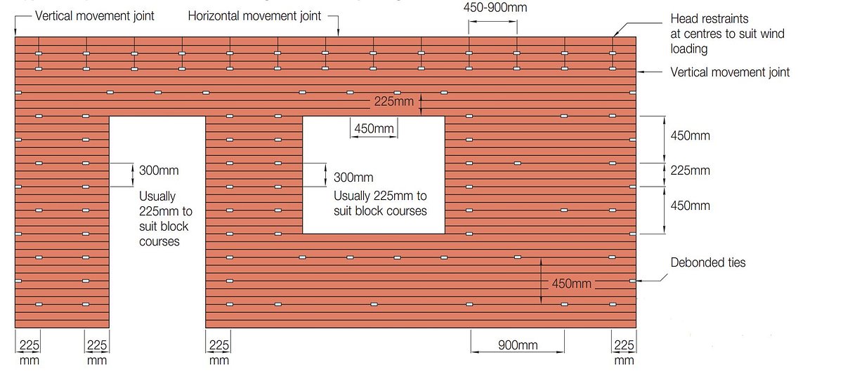
Standard spacing for cavity brickwork 900mm x 450mm centres in a staggered pattern (2.5 ties per square metre)
Change the wall tie pattern around openings such as windows, doors, roof verges, unreturned or unbonded edges and un-tied vertical movement joints. Here the vertical spacing is reduced to a maximum of 300mm and ties should not be more than 225mm from the edge of the opening. This often means there is a wall tie every course of blocks within 225mm of the opening. Spacing at vertical movement joints may be relaxed where the joint has a debonded tie spanning it. Please refer to Ancon’s technical literature for further details.
Timber frame ties

Timber Frame Movement Tie
An important factor in the design of timber frame ties is the allowance for vertical movement. As timber frames tend to shrink and expand seasonally, the wall tie should be flexible enough to cope with this differential movement. Therefore it is important to select the right tie to suit the amount of movement expected in the building. Tie types 5 and 6 (Ancon references STF6 and TIM6) allow for 24mm of frame shrinkage and are suitable for most timber frame buildings up to four storeys high. Our Type 7 (Ancon reference TFMT7) is designed for use in larger buildings, offering a movement allowance of up to 65mm.
Timber frame ties should be installed at a minimum density of 4.4 ties per square metre in buildings where the basic wind speed does not exceed 25m/s (BS 6399-2:1997 Code of Practice for Wind Loads). The density should be increased to 7 ties per square metre in more severe situations, however Ancon recommends that, where the project falls outside of the scope of the tables displayed in our literature, a structural engineer should be consulted on the tie specification and spacing.
Similar practices at openings and unbonded edges are applied with timber frame ties.
Ties for cold-formed steel frames

25/14 Restraint System
Ancon’s 25/14 restraint system is designed for use with cold-formed steel frames. This is a channel and tie system where the channels are placed vertically at stud positions. The system is designed to be installed at a maximum of 600mm horizontal spacing to match the typical spacing of the steel studs. The vertical spacing of wall ties and fixing screws should be no greater than 450mm, with this dimension reducing to accommodate higher wind loads (e.g. in taller buildings). Please refer to Ancon’s technical literature for further details.
Wall Ties and Restraint Fixings (PDF, 8.12 MB)
Latest News
New Ancon Molabolt – The Next‑Generation Fixing for Masonry Support Steel Applications.
Leviat is pleased to announce the launch of the Ancon Molabolt, a new high‑performance fixing designed specifically for Ancon masonry support systems and steel fabrications. Developed to deliver exceptional installation speed, improved handling and verified engineering performance, the Ancon Molabolt represents the next evolution in fixing technology for the construction sector.
Leviat Expands Its Range of Non-Combustible Clips
Leviat, leading manufacturer of engineered construction solutions, has launched its second non-combustible clip to the range - the Ancon A1-S Insulation Retaining Clip. This new A1-rated, non-combustible clip has been specifically designed for use with Ancon flat wall ties, including SDB, SD21 and YDB.
1 comment
Please leave a comment using the form below
Loft Boarding Specialist
Great blog. Looking forward to more ideas.